ECE 4160 Fast Robots
Raphael Fortuna
Lab reports made by Raphael Fortuna @ rafCodes Hosted on GitHub Pages — Theme by mattgraham
Home
Lab 3: Time of Flight Sensors
Summary
In this lab, I soldered each of the two time of flight (ToF) sensors to QWIIC connectors, tested each sensor’s I2C connection and range performance, setup the ToF sensors to run together, added ToF functionality to the Bluetooth code, and graphed my time-series ToF data from each sensor.
Prelab
The sensor’s I2C address in the manual was listed as 0x52. Functions for changing the distances and other setting for each ToF sensors were also discussed, like the timing for measurements.
I will change the address programmatically for one of the two sensors by using the shutdown pin. One sensor will be turned off while the other will have its address reprogrammed as discussed later below. This is because each time a sensor is turned off, it loses any settings applied to it and must wait a short time while it calibrates itself and gets setup. By giving it a different address, the extra wait time would be at the beginning when other initializations are happening and let the sensors gather data faster during the robot’s runtime instead of turning a ToF sensor off and on and waiting when a measurement is needed.
I will place the two sensors on the front of the robot at different outward angles so that the robot can spin around and detect different obstacles while having some side and forward obstacle detection at the same time. A scenario where this would miss obstacles includes hitting obstacles while reversing or having an obstacle be too close such that both beams are not hitting the obstacle since they are angled outwards. I will be using the long wires so that the location can easily be changed if needed.
Installation and Assembly Task
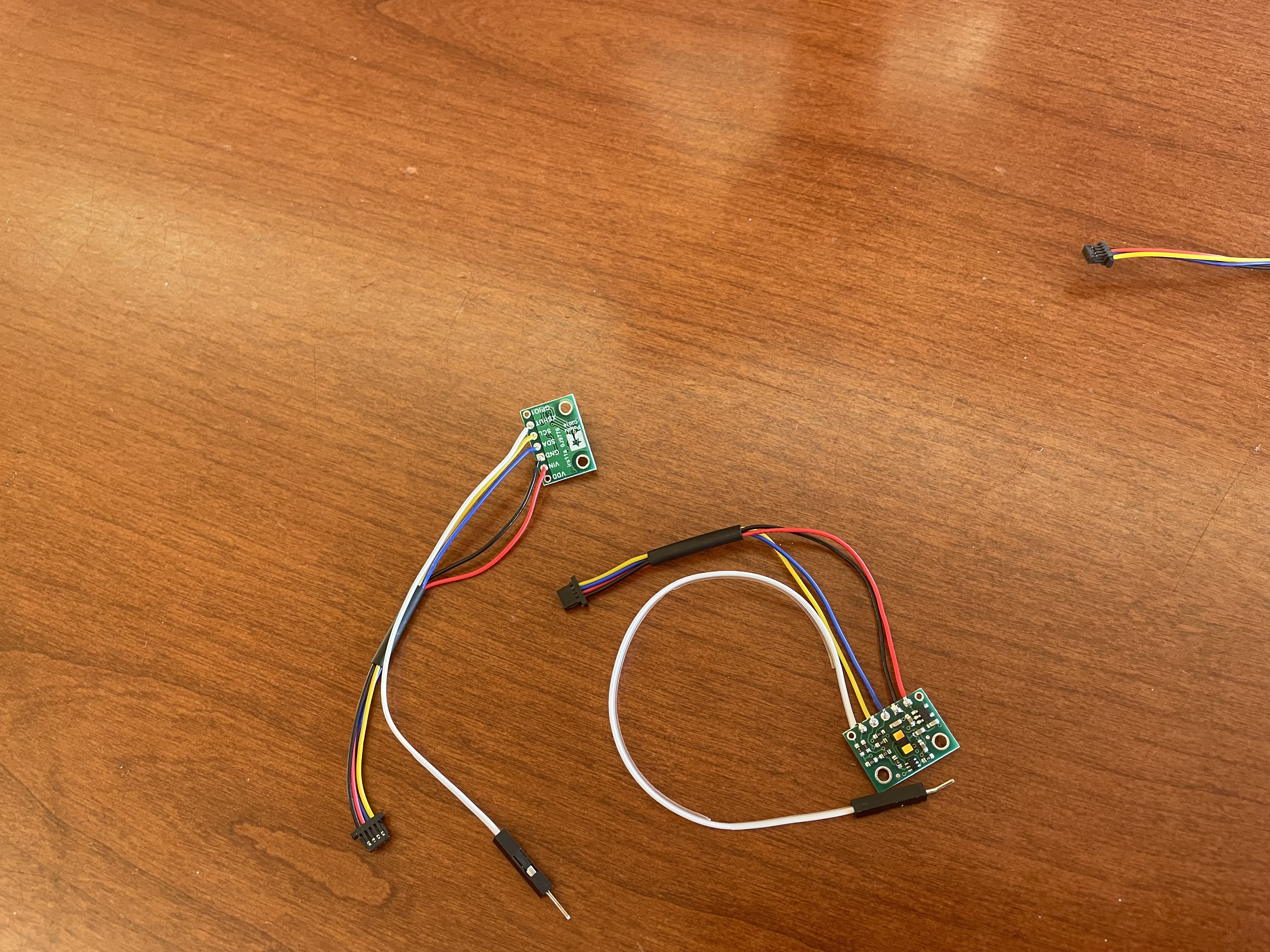
I first installed the SparkFun VL53L1X 4m laser distance sensor library. Next, I looked up the pin diagram for the QWIIC connector on Sparkfun’s website and found that black is ground, red is vin, blue is SDA, and yellow is SCL. I cut one end off of each QWIIC connector and soldered them to the respective ends of the ToF sensor as seen below. I also soldered a jumper cable to the XSHUT shutdown pin so that one ToF sensor could be turned off to reprogram the I2C address of the other sensor. I chose the long connector since this would give me flexibility in where I could put the TOF sensor on the robot.
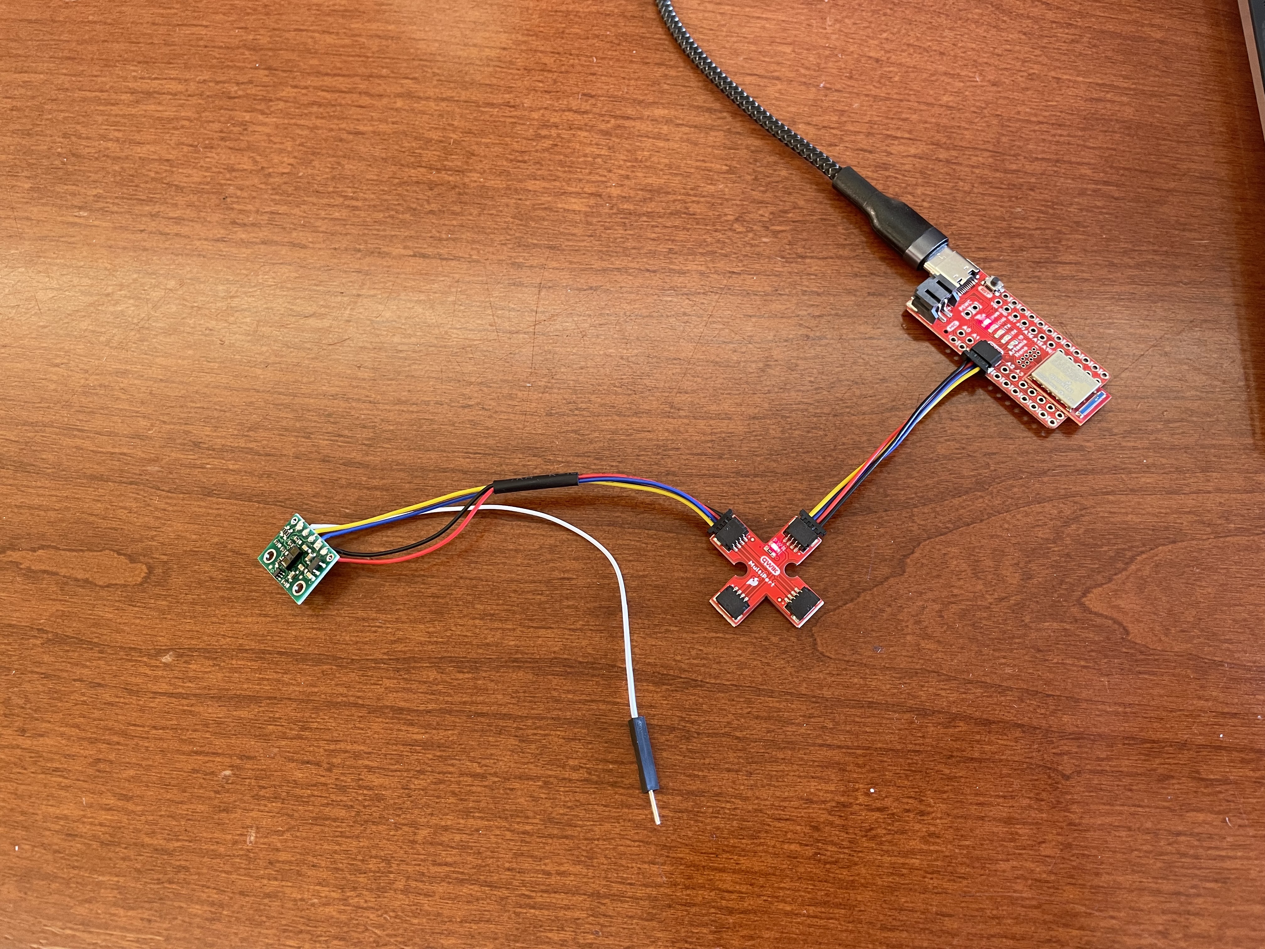
I then connected the first ToF sensor to the QWIIC breakout board.
Scanning Task
When I ran the Example1_wire code in Apollo3, it said the address of the ToF sensor was 0x29. The code looped through addresses from 1 to 127 and checked if there was a return value from the transmissions using a Wire.h and i2c.

The datasheet talked about how the correct address should be 0x52 instead of 0x29.
However, the last bit is the R/W bit, so as Anaya mentions in her website: https://anyafp.github.io/ece4960/labs/lab3/ the address is bit shifted so now it is 0x29 for the address. This is the same address for both of the ToF sensors.
Range Optimization Task
The three modes for measuring distance are: short, medium, and long as from the datasheet.
Short measures distances up to 1.3 m and has better resistance to ambient influences. Medium measures distances up to 3 m. Long measures distances up to 4 m and is the default mode for the ToF sensor. The sensor measurement that works the best depends on the tasks needed for the final robot. For localization, more distance is needed to scan around the robot so the long mode would be good. For any tasks before the final tasks that need to be near a wall to stop or flip, then the short mode would be helpful instead to be more accurate.
The datasheet also discussed how the medium and long settings had their ranges go down to 76 cm and 73 cm for their maximum range under strong ambient light while the short distance mode only lost 1 cm of range to 135 cm. So, if it is very bright out then the short distance mode should be used as it will have the longest range.
Range Testing Task
I used the Example1_ReadDistance example from the ToF sensor examples to test a sensor. I added a extra line to the initialization to set the mode to short with distanceSensor.setDistanceModeShort();. I also added code to get the start and end time of the reading to get the average ranging time.
For the sensor range, the max range should be 136 cm, so I walked backwards from the sensor holding a folder to see how the distance changed. As I went further past the maximum range, the sensor readings dropped swiftly to near 0 and then stayed around 200 millimeters at around 4.5 meters of distance. This means that the ToF sensor cannot measure outside its given range for short and has good repeatability from the graph below. There is a time shift on the x axis from how fast I was moving from the sensor and one sensor reading did not make it past 1200 millimeters, so the sensor should not be used near its max range.
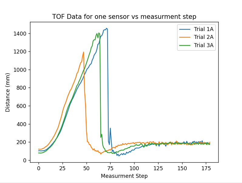
The ranging time for the sensor was 33 milliseconds on average during these measurements.
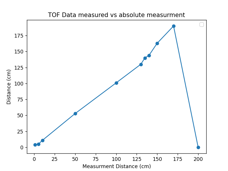
I also took 11 measurements where I compared the distance measured using a measuring tape vs the ToF sensor. I found that the measurements were not as reliable and differed by 2-3 cm when measuring very close to the sensor, but in the mid-range between 10 cm and 130 cm, were accurate. After passing the 136 cm limit for the short range mode, the readings starting differing by 10 cm or more until the sensor no longer registered a distance at 200 cm, similarly to the graph above.
Running both ToF Sensors together Task
To run both sensors together, I decided to use the XSHUT pin to turn off one of the sensors temporarily so that I could change the I2C address. I followed the steps on Anaya’s website (https://anyafp.github.io/ece4960/labs/lab3/) and used the 0x32 address for my second sensor.
I created an initialization function for the ToF sensors in Arduino and then created functions to print each of them out to the console only when data was available.
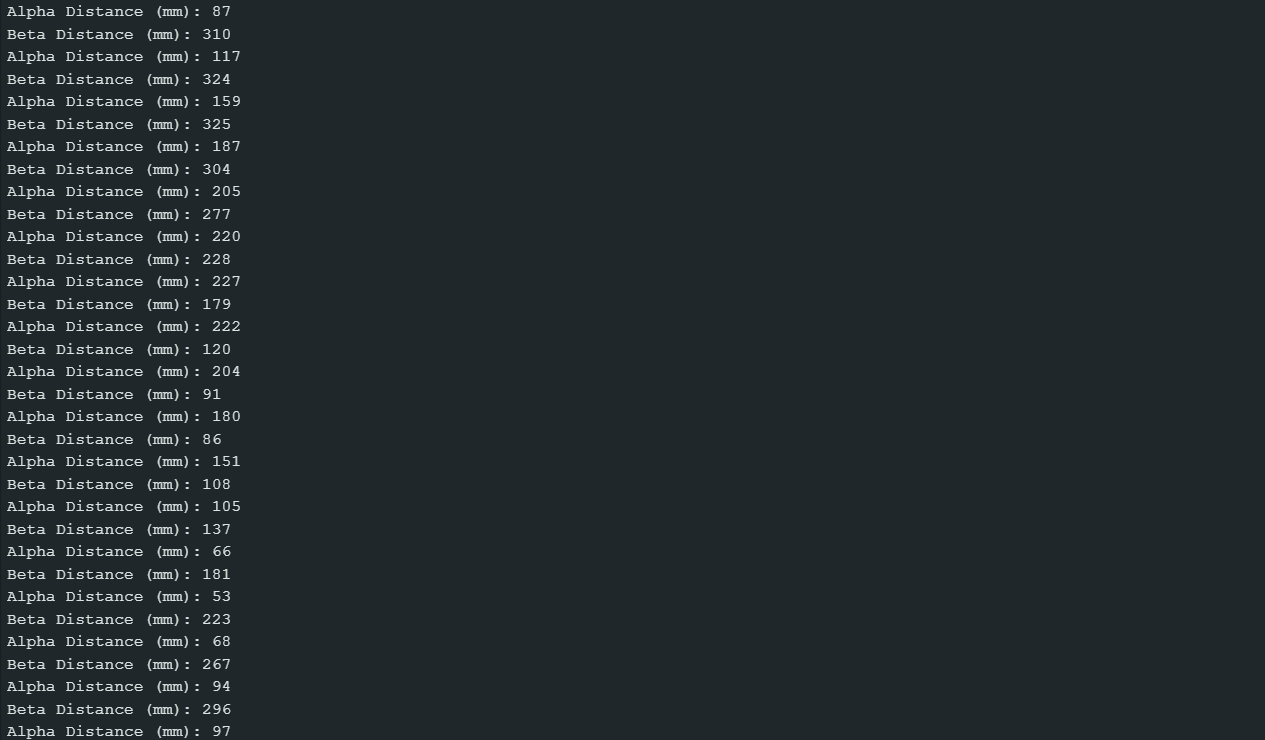
Here is a picture of the data from each sensor being printed:
ToF Sensor Speed Task
I used the functions from the previous task and added a print statement for milliseconds, otherwise, it skipped printing sensor data. It printed the Artemis clock each time it cycled through each ToF sensor as seen above commented out.
A picture of the output from the sensors and Artemis clock can be seen below, with the values under 500 as the sensor measurments:
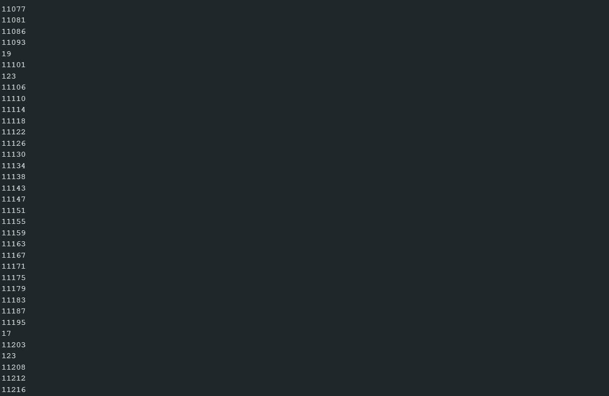
The time for the loop to execute was 102 milliseconds. The limiting factor for this loop seems to be the timing defaults for the ToF sensor. From the datasheet, the timing budget is how long it takes the sensor to perform one range measurement and the inter-measurement period is the delay between each ranging measurement. By decreasing the inter-measurement period, the ToF sensor would measure the distance more often, reducing the loop time. The ranging timing could also be decreased depending on the distance mode; however, this could mess up the measurement if it is too small, so the inter-measurement period is the better choice.
Graphing ToF Task
For this task, I added a new file to the Artemis Bluetooth project and made the ToF functions standalone so that they could be modified or changed without having to update the Bluetooth file. I added a command called SEND_TOF_DATA_FOR_X to the Python and Arduino enums which would send ToF data for a given amount of seconds back to the laptop.
I used a similar method to the previous task to get ToF data and would loop and wait until a sensor reading was ready and then sent sensor readings in sets of 4. I formatted each reading with TOF_ with the _ either being A (Alpha) or B (Beta) depending on which sensor the reading was done with.
Once I was able to send ToF data to my laptop, I added code to save and process the data and separate the data from sensors A and B by using the letters added to distance label.
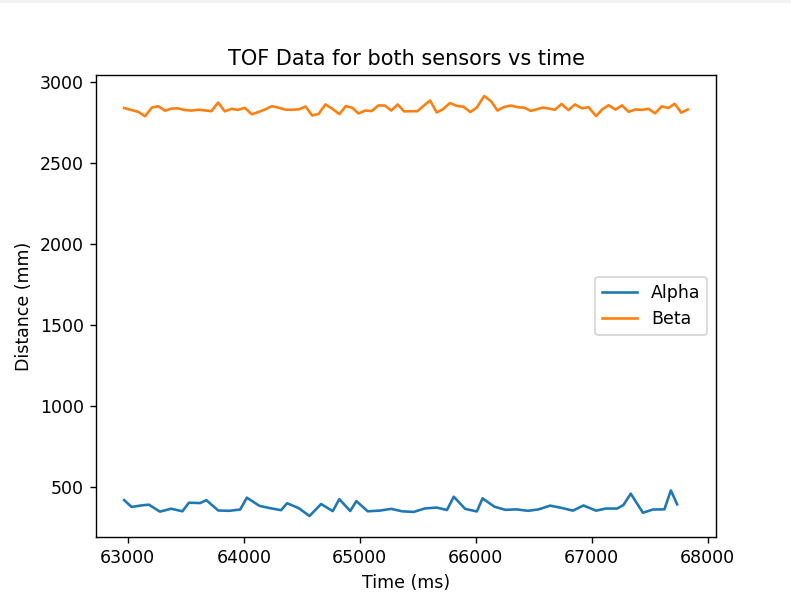
Here is data from the two ToF sensors sent via Bluetooth and processed by my Python code. The Alpha sensor was pointing towards a near wall while the Beta sensor was pointing towards a far wall.
